How to Draw a Jar in Autocad
AutoCAD Tutorial: Create a mesh solid jar
This tutorial requires AutoCAD 2010 or later and shows how to create a mesh solid jar.
- Start a new drawing using acad3d.dwt.
- Switch to the 3D Modeling workspace by choosing it from the Workspace Switching pop-up menu on the right side of the status bar or next to the Quick Access toolbar at the upper-left corner of your screen.
- Check that the tessellation divisions are the default 3 in each direction by clicking the Mesh Modeling tab, and then the dialog box launcher arrow at the right end of the Primitives panel title bar. Click OK.
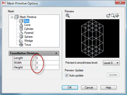
- Still on the Mesh Modeling tab, in the Primitives panel, click Mesh Box. Follow the prompts:
Specify first corner or [Center]: Click anywhere on the XY plane.
Specify other corner or [Cube/Length]: c (for the Cube option)
Specify length: 2
- My mesh cube was rotated so I use the ROTATE command, selected the cube, specified a corner for the base point, and then used the Reference option. At the Specify the reference angle <0>: prompt, I picked one corner, and at the Specify second point: prompt, I picked the next corner. At the Specify the new angle or [Points] <0>: prompt, I pressed Enter to align the cube with the X axis.
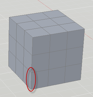
- In the Subobject panel, choose Edge from the Object Filter drop-down. Then choose Move Gizmo just to the right.
- Hold down the Ctrl key and click the bottom edge of any corner, circles in the above image. The Move Gizmo appears.
- Move your cursor until the XY plane (yellow) highlights, then push inward (into the cube). At the Specify stretch point or [Base point/Undo/eXit]: prompt, type .25.
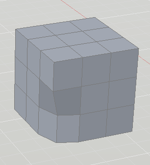
- Repeat for the other corners, being careful to deselect the previous edge first by pressing Esc. I hold Shift and my mouse's wheel to transparently orbit, but you can use any method to change the viewpoint and access the other corners.
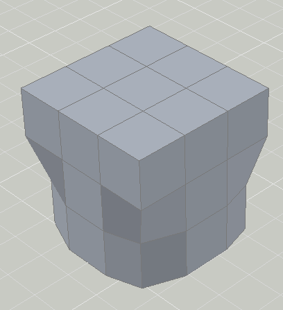
- In the Subobject panel, switch to the Face filter and the Scale Gizmo.
- Select the top center face. The Scale Gizmo appears. Select the XY plane (it becomes yellow — this isn't always easy, but keep trying). At the Specify scale factor or [Base point/Undo/Reference/eXit]: prompt, enter 2.
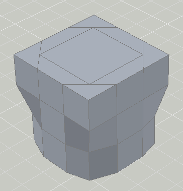
- On the Mesh Modeling tab, Mesh panel, click Smooth More. Select the mesh solid, and end selection.
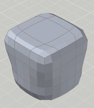
- To create the neck of the jar, choose Extrude Face from the Mesh Edit panel. Ctrl-select the top middle face and drag it upward. At the Specify height of extrusion or [Direction/Path/Taper angle] <2.0000>: prompt, enter .75.
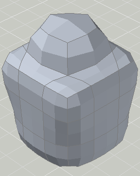
- To flatten the top, choose Add Crease from the Mesh panel. Ctrl-select the top, middle face and end selection. At the Specify crease value [Always] <Always>: prompt, press Enter.
- On inspection, it seems like it could use more smoothing, so choose Smooth More again and select the model.
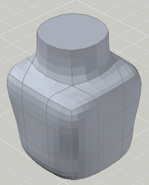
I wanted to shell out the inside, but every time I tried, AutoCAD stalled or told me "No solution for an edge." You can try it at your own risk:
- On the Convert Mesh panel, choose Convert to Solid.
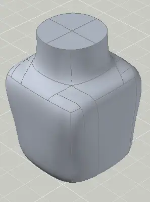
- On the Home tab, Solid Editing panel, click the bottom drop-down list and choose Shell. Select the solid and end selection.
- At the Remove faces or [Undo/Add/ALL]: prompt, select the top faces. I find this difficult to impossible.
- At the Enter the shell offset distance: prompt, enter .1.
I also tried making a copy, scaling it down, putting the smaller version inside the larger one, and using the SUBTRACT command. I wasn't successful with that either. I'm open to suggestions. Leave a comment!
- Author
- Recent Posts
![]()
5 comments to AutoCAD Tutorial: Create a mesh solid jar


Source: https://allaboutcad.com/autocad-tutorial-create-a-mesh-solid-jar/


0 Response to "How to Draw a Jar in Autocad"
Postar um comentário